How to Choose a Planetary Gearbox for Your Application?
Choosing a planetary gearbox starts with the machine’s real working conditions, not just a catalog rating. A conveyor moving steady loads has different needs from a robot arm that starts, stops, and changes direction all day. Define the required output torque, speed, and reduction ratio. Then consider how often the system runs and how sharply its load changes. Small details matter.
A Gearbox Planetary Gear can provide high torque in a compact space, but the right model depends on more than its size. Check the gearbox’s rated and peak torque, allowable input speed, backlash, and expected service life. Confirm that the mounting arrangement fits the available space, and review radial and axial load limits where pulleys or external forces are involved. Heat, dust, vibration, and limited maintenance access can also affect performance. A neat calculation may still miss a harsh start-up or a load that changes by the hour.
Compare these requirements with technical data from the manufacturer, and ask for clarification when ratings or test conditions are unclear. Use the motor’s actual operating range, not only its maximum nameplate value. Leave a sensible margin, but avoid oversizing without a reason; it can add cost and may affect efficiency. Real installations are rarely perfect. Cable routing, alignment, and unexpected duty cycles deserve a second look. The best choice is the one whose documented limits match the application and whose performance can be checked after installation.
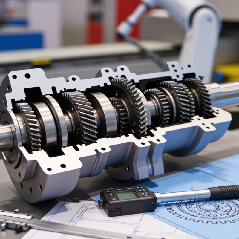
Define Required Output Torque, Speed, Duty Cycle, and Radial Loads
Start with the load at the gearbox output, not just the motor rating. Record continuous torque and peak torque during starts, stops, or jams. Peaks matter. A conveyor carrying wet material, for example, may need brief high torque even when its average load is modest. Include the required output speed, and check that it stays within the gearbox’s rated range under real operating conditions.
Duty cycle changes the selection. Note daily running hours, starts per hour, reversal frequency, and time spent near peak load. A gearbox running intermittently may tolerate a different thermal load than one operating continuously. Measure the actual cycle if possible; estimates from a neat spreadsheet can miss pauses or sudden load changes. That happens. Also account for ambient temperature and available cooling, since heat can reduce allowable torque.
Check radial loads at the output shaft, including belt tension, chain pull, or an overhung pulley. Compare the load with the gearbox’s permitted radial force at the actual distance from the mounting face. Moving a pulley outward increases bearing load, even when belt tension stays unchanged. Confirm axial loads too, if the application creates them. Share these figures, plus mounting position and expected service life, with a qualified gearbox supplier. A small mismatch in assumptions can matter.
Calculate the Gear Ratio from Motor Speed and Target Output Speed
How to Choose a Planetary Gearbox for Your Application?
Calculate the Gear Ratio from Motor Speed and Target Output Speed
Start with the motor’s operating speed and the output speed your machine needs. Divide motor speed by target output speed to estimate the required reduction ratio. Keep both speeds in the same units, usually revolutions per minute (rpm). For example, a motor running at 1,800 rpm and a target output of 60 rpm needs a ratio of 30:1. Check the units.
Use the motor’s actual operating speed, not just the number on its nameplate. A variable-speed drive may run the motor below its rated speed. Measure or confirm the expected speed under normal conditions. Then compare the calculated ratio with available gearbox ratios. A 29:1 or 31:1 option may be more practical than an exact match, but it will change output speed. At 1,800 rpm, a 31:1 ratio gives about 58 rpm.
The calculation is a useful starting point, not the whole selection. Load, acceleration, and motor speed changes can affect real operating performance. A paper calculation can still miss what happens when a conveyor starts with product on it. Check the gearbox’s rated input speed and output torque, and allow for the machine’s duty cycle. If the output speed must stay precise, confirm the motor’s speed control and measure the assembled system during testing.
Compare Single-Stage Ratios of About 3:1–10:1 with Multistage Options
Single-stage planetary gearboxes commonly cover ratios from about 3:1 to 10:1. This range can suit conveyors, indexing tables, and compact actuators that need moderate speed reduction. At 5:1, for example, the output turns roughly once for every five motor turns, before considering operating conditions. A single stage is often compact and efficient, with fewer components to manage. But the ratio alone does not confirm suitability. Check required output torque, input speed, duty cycle, and allowable backlash against the gearbox specifications.
When more speed reduction is needed, multistage configurations combine gear stages to reach higher overall ratios. They can deliver slower output and greater torque multiplication, but added stages may increase length, losses, heat, and backlash. The trade-off matters in a machine that starts and stops frequently or holds a precise position. Measure the available mounting space, too. A higher ratio can solve a speed problem while creating a packaging problem. I have seen this detail overlooked.
Tips: Start with the motor speed and target output speed; their relationship gives a practical ratio estimate. Then check peak torque, not only continuous torque. Leave margin for shock loads and real operating conditions. Published ratios may be nominal, so verify the exact configuration before choosing.
How to Choose a Planetary Gearbox for Your Application? - Compare Single-Stage Ratios of About 3:1–10:1 with Multistage Options
| Configuration | Typical Total Ratio | Example Stage Combination | Approx. Efficiency* | Often Suited To | Main Trade-Off |
| Single stage | About 3:1–10:1 | 5:1 | About 97% | Moderate speed reduction where compactness, efficiency, and low backlash are priorities | Limited reduction per stage; may not deliver enough output torque at very low speeds |
| Two stage | Commonly about 9:1–100:1 | 5:1 × 5:1 = 25:1 | About 94% with 97% per stage | Applications needing higher torque and lower output speed, such as indexing axes or compact conveyors | More components and cumulative losses than a single-stage unit |
| Three stage | Commonly about 27:1–1,000:1 | 5:1 × 5:1 × 5:1 = 125:1 | About 91% with 97% per stage | Large reductions for slow, high-torque outputs when a direct-drive motor is impractical | Typically lower overall efficiency and greater complexity; check thermal and duty-cycle limits |
| Ratio selection check | Approx. output speed = motor speed ÷ reduction ratio | For example, a 1,500 rpm motor with a 25:1 reduction gives approximately 60 rpm at the gearbox output, before considering load-dependent speed variation. |
| Torque and service check | Confirm rated output torque, peak torque, and duty cycle | Allow for acceleration, shock loads, mounting orientation, ambient temperature, and the required service life—not just the nominal ratio. |
*Efficiency figures are illustrative estimates based on roughly 97% efficiency per stage. Actual efficiency, available ratios, backlash, torque capacity, and permissible speed depend on gearbox design, size, lubrication, operating conditions, and manufacturer specifications.
Check Rated Torque, Peak Torque, Backlash, and Efficiency per Stage
A planetary gearbox can survive a brief torque spike and still fail under a lower, continuous load. Compare application torque with both the gearbox’s rated output torque and its peak limit. Rated torque must cover the real duty cycle, including starts, reversals, and sustained low-speed operation. Peak torque is for short events, not a substitute for continuous capacity. ISO 6336-1:2019 describes methods for evaluating gear load capacity; use the applicable rating method and confirm the manufacturer’s stated conditions.
Backlash affects positioning. A gearbox with 3 arcminutes of backlash produces about 0.087 mm of angular lost motion at a 100 mm radius. That may be acceptable for a conveyor, but visible in a small indexing fixture. Check backlash at the output shaft and at the operating load, not just in a no-load specification. One detail is easy to miss: mounting stiffness and coupling play can add to the total error.
Efficiency also compounds across stages. As a screening calculation, two stages at an assumed 98% efficiency each deliver about 96% overall, before other losses. That is an estimate, not a guarantee. Lubrication, speed, temperature, and load matter. AGMA 6001-F19 provides guidance for selecting enclosed gear drives; use test data for the actual gearbox where available. A slightly imperfect estimate is still better than ignoring heat: at 1 kW input, 4% loss becomes roughly 40 W to dissipate.
Assess Bearing Life Using ISO 281’s L10 Rating and Mounting Constraints
When choosing a planetary gearbox, use ISO 281’s L10 rating to assess its rolling-bearing life. L10 represents the life that 90% of a sufficiently large group of identical bearings is expected to reach under specified conditions. It is a statistical estimate, not a promised service interval. Not the whole gearbox. Gear teeth, seals, lubricant, and operating temperature may limit service life sooner.
Start with the bearing loads implied by your application: radial force, axial force, torque, speed, and duty cycle. A conveyor that runs steadily differs from an indexing table with frequent starts and stops. Ask the supplier which load assumptions and lubrication conditions support the stated L10 value. Small changes matter. Shock loads, contamination, high temperature, or poor lubrication can reduce actual bearing life.
Then check whether the gearbox can fit and operate correctly in its intended mounting position. Confirm shaft orientation, available space, support stiffness, and permitted radial or axial loads at the output shaft. Belt tension or a long overhung load can add force the gearbox rating does not cover. Alignment matters, too. In practice, installation details are easy to underestimate; measure the real loads and leave access for inspection before finalizing the selection.
How to Choose a Planetary Gearbox: ISO 281 Bearing Life and Mounting Constraints
Illustrative L10 life estimates for four ball-bearing design scenarios at an equivalent dynamic bearing load of 4.0 kN. Compare the estimated life with your duty cycle and available mounting space.
The estimates use the ISO 281 basic rating life relation for ball bearings: L10 = (C/P)3 million revolutions, converted to hours using bearing speed. L10 represents 90% reliability under the rating assumptions, not a guaranteed service life. Before selecting a gearbox, confirm bearing type, actual loads and speed, lubrication, required reliability, shaft and housing fits, and radial, axial, and overall mounting clearances. Values below are illustrative, not product specifications.
