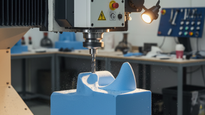
| Machine Definition |
Primary function |
Automated material removal or forming performed according to programmed tool paths. |
Provides repeatable production with limited manual intervention. |
| Machine Definition |
Typical large-machine application |
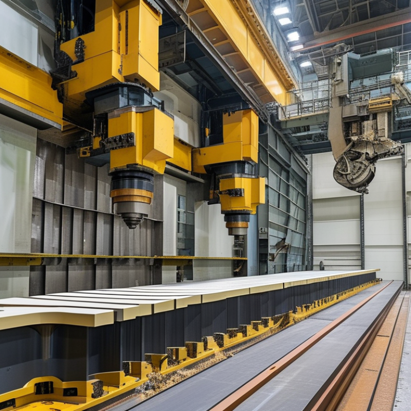
Machining large plates, frames, molds, structural parts, housings, shafts, and industrial equipment components. |
Allows large workpieces to be processed without repeated repositioning. |
| Machine Size |
Working envelope |
Common large-format machines may provide approximately 2,000–10,000 mm of travel on one or more linear axes, depending on configuration. |
Determines the maximum part dimensions that can be machined. |
| Machine Size |
Worktable capacity |
Table size and load capacity vary widely; heavy-duty tables may support several tonnes when the load is evenly distributed and properly secured. |
Ensures the machine can safely support the workpiece, fixtures, and cutting forces. |
| Machine Structure |
Machine bed and frame |
Usually constructed from rigid cast or fabricated structures designed to resist vibration, deflection, and thermal movement. |
Rigidity directly affects dimensional accuracy and surface finish. |
| Machine Structure |
Common machine configurations |
Large vertical machining centers, horizontal machining centers, gantry machines, bridge mills, and large CNC lathes. |
The configuration is selected according to part geometry, size, weight, and access requirements. |
| Motion System |
Linear axes |
X, Y, and Z axes provide controlled movement along three perpendicular directions. |
Coordinate movement creates the programmed cutting path. |
| Motion System |
Rotary axes |
Optional A, B, or C axes rotate the workpiece or cutting tool around a linear axis. |
Enables multi-sided machining and the production of complex surfaces. |
| Motion System |
Positioning feedback |
Linear scales, rotary encoders, or other feedback devices measure axis position for closed-loop control. |
Improves positioning accuracy and helps detect motion errors. |
| Spindle System |
Spindle function |
The spindle rotates the cutting tool or workpiece at a programmed speed while transmitting cutting torque. |
Controls cutting speed, material removal capability, and surface quality. |
| Spindle System |
Typical speed range |
Large heavy-duty machining spindles often operate from several hundred revolutions per minute to approximately 8,000–12,000 revolutions per minute, depending on the application. |
Lower speeds support high-torque roughing; higher speeds support smaller tools and finishing. |
| Spindle System |
Tool holding |
Cutting tools are secured in a holder, chuck, collet, or other approved retention system compatible with the spindle. |
Secure retention reduces tool movement, vibration, and runout. |
| Control System |
Program input |
Computer-aided manufacturing software generates tool paths that are converted into machine-readable numerical control code. |
Translates the digital part design into coordinated machine movements. |
| Control System |
Coordinate system |
The work offset establishes the relationship between the part datum and the machine coordinate system. |
Correct offsets are essential for cutting at the intended locations. |
| Control System |
Feed rate |
Feed rate is the programmed speed at which the tool advances through the material, commonly specified in mm/min or in/min. |
It influences cutting force, tool life, chip formation, and productivity. |
| Control System |
Cutting speed |
Cutting speed is the relative surface speed between the cutting edge and the workpiece, commonly expressed in m/min or surface feet/min. |
Must be matched to the tool material, workpiece material, and cutting operation. |
| Cutting Parameters |
Depth of cut |
Axial depth of cut describes how deeply the tool engages along its axis; radial depth describes the width of engagement. |
Higher engagement increases material removal but also increases cutting load. |
| Cutting Parameters |
Chip load |
Chip load is the material thickness removed by each cutting tooth during one revolution, calculated from feed rate, spindle speed, and tooth count. |
Helps prevent rubbing, excessive heat, tool breakage, and poor chip formation. |
| Materials |
Common workpiece materials |
Carbon steel, stainless steel, aluminum alloys, cast iron, copper alloys, titanium alloys, engineering plastics, and composite materials. |
Material properties determine tool selection and cutting parameters. |
| Materials |
Material preparation |
The workpiece should be inspected for scale, distortion, excessive stock, hard spots, and surface contamination before machining. |
Preparation reduces setup errors and unexpected tool wear. |
| Tooling |
Roughing tools |
High-feed cutters, face mills, end mills, drills, and turning tools are commonly selected to remove large amounts of material efficiently. |
Roughing establishes the basic shape and leaves stock for finishing. |
| Tooling |
Finishing tools |
Ball-nose end mills, finishing end mills, reamers, boring tools, or fine turning tools may be used for final dimensions and surface quality. |
Finishing improves dimensional accuracy and surface appearance. |
| Workholding |
Fixture selection |
Fixtures may include vises, clamps, modular plates, vacuum systems, chucks, steady rests, or custom supports. |
A rigid fixture prevents movement and protects the workpiece from distortion. |
| Workholding |
Datum establishment |
Reference surfaces or probing cycles are used to establish the X, Y, and Z origin of the workpiece. |
Provides a repeatable reference for all programmed coordinates. |
| Operation Step 1 |
Review the design and process plan |
Confirm part dimensions, tolerances, material, machining sequence, required tools, inspection points, and allowable stock. |
Prevents programming and setup decisions that conflict with drawing requirements. |
| Operation Step 2 |
Create the tool path |
Generate roughing, semi-finishing, finishing, drilling, tapping, boring, or turning paths using the digital part model. |
Defines the exact route and cutting behavior of each tool. |
| Operation Step 3 |
Simulate and verify the program |
Check for collisions, excessive tool engagement, over-travel, incorrect sequencing, insufficient clearance, and remaining stock. |
Reduces the risk of machine damage and scrapped parts. |
| Operation Step 4 |
Prepare the machine |
Inspect lubrication, coolant, guarding, emergency stops, tool condition, work area cleanliness, and machine power status. |
Confirms that the machine is ready for safe operation. |
| Operation Step 5 |
Load and secure the workpiece |
Position the workpiece on the table or chuck, install approved supports, and tighten the workholding system according to the setup plan. |
Prevents shifting, vibration, and unsafe movement during cutting. |
| Operation Step 6 |
Load and measure tools |
Install the required tools and enter or measure tool length, diameter, radius, orientation, and wear offsets. |
Correct tool data ensures that the programmed path matches the actual tool geometry. |
| Operation Step 7 |
Set the work coordinate system |
Locate the programmed datum using an edge finder, probe, indicator, touch-off method, or verified reference feature. |
Aligns the digital program with the physical workpiece. |
| Operation Step 8 |
Perform a dry run or single-block check |
Run the program with the tool clear of the workpiece or use reduced rapid and feed rates to verify movement. |
Provides a final check for incorrect offsets, clearances, and motion commands. |
| Operation Step 9 |
Start the cutting cycle |
Begin with conservative cutting conditions, observe chip formation, listen for vibration, and monitor spindle load and coolant flow. |
Early monitoring helps identify unstable cutting before major damage occurs. |
| Operation Step 10 |
Rough machining |
Remove bulk material using suitable stepdowns, stepover values, spindle speed, and feed rate while leaving a controlled amount of stock. |
Efficiently reduces the part to a near-final shape. |
| Operation Step 11 |
Finishing and secondary operations |
Complete finishing passes, drilling, tapping, boring, chamfering, contouring, or multi-axis features as specified by the process plan. |
Produces final geometry, tolerances, and surface finish. |
| Operation Step 12 |
In-process inspection |
Measure critical dimensions using probes, calipers, micrometers, gauges, or coordinate measuring equipment where appropriate. |
Allows corrective adjustments before the complete batch is produced. |
| Operation Step 13 |
Part removal and cleaning |
Stop the machine, wait for complete spindle and axis movement to cease, remove the part safely, and clear chips using approved methods. |
Protects operators and prevents chips from interfering with subsequent setups. |
| Operation Step 14 |
Final inspection and documentation |
Verify dimensions, tolerances, surface condition, feature locations, and traceability records against the approved requirements. |
Confirms conformity before the part is released. |
| Accuracy Factors |
Thermal effects |
Heat from the spindle, motors, coolant, environment, and cutting process can cause machine or workpiece expansion. |
Warm-up routines, temperature control, and compensation help maintain accuracy. |
| Accuracy Factors |
Machine alignment |
Leveling, geometric alignment, backlash condition, spindle runout, and axis calibration influence final part accuracy. |
Regular verification is important for large machines with long travel distances. |
| Safety |
Required precautions |
Use guarding, eye and hearing protection, appropriate footwear, safe chip-removal tools, and approved lifting equipment; keep clear of moving parts. |
Large machines involve high stored energy, heavy loads, rotating tools, and substantial cutting forces. |
| Maintenance |
Routine maintenance |
Check lubrication, coolant concentration, filters, way covers, tool holders, hydraulic or pneumatic systems, electrical connections, and chip removal systems. |
Routine maintenance reduces unplanned downtime and preserves machining performance. |