Skip to content

Why Choose a CNC Vertical Turning Lathe?

Why Choose a Cnc Vertical Turning Lathe?

Choosing a Cnc Vertical Turning Lathe begins with the workpiece, not the machine brochure. Large, heavy components often sit more securely on a vertical spindle. Gravity helps hold them against the chuck. This matters when machining bearing housings, wheel hubs, gears, flanges, and turbine components. The operator can also load parts with less awkward lifting. That practical advantage becomes important during long production shifts.

Gene Haas, founder of Haas Automation, has often emphasized a clear manufacturing principle: “The key to our success is to make the best machines at the lowest possible price.” His statement reflects an essential buying question. Does the machine deliver measurable value through accuracy, uptime, accessibility, and repeatability? A Cnc Vertical Turning Lathe should provide more than impressive specifications. It should maintain stable cutting when interrupted surfaces create vibration. It should also support efficient chip evacuation and dependable tool changes.

In real workshops, details decide performance. A rigid bed reduces movement during roughing cuts. A powerful spindle handles demanding material removal. Automatic probing can detect setup errors before they become expensive scrap. Yet no lathe solves every problem. Floor space, operator training, tooling costs, and maintenance still require honest evaluation. Sometimes, a horizontal machine may fit better. That is worth admitting.

The strongest choice matches machine capacity with actual production needs. Review part diameter, material, tolerances, batch size, and loading methods carefully. Then compare proven results, not marketing language. A well-selected Cnc Vertical Turning Lathe can improve consistency, safety, and production flow when its design fits the job.
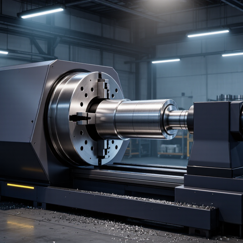
Why Choose a CNC Vertical Turning Lathe?

What Defines a CNC Vertical Turning Lathe in Modern Manufacturing

A CNC vertical turning lathe is defined by its upright machining structure, not simply by computer control. The spindle holds the workpiece on a horizontal table, while cutting tools move along controlled vertical and radial axes. This arrangement supports large, heavy components because gravity helps seat the workpiece against the chuck. Modern machines combine servo drives, digital feedback, programmable tool paths, and automatic measurement routines. Operators can repeat turning cycles accurately, even when diameters, grooves, and facing operations share one setup. That reduces handling and helps maintain consistent surfaces across production batches. Still, accuracy depends on calibration, tool condition, fixture alignment, and a realistic cutting strategy. The machine cannot correct poor judgment.

In practical workshops, the vertical layout improves access to broad faces and simplifies loading with lifting equipment. A rigid column and stable table reduce vibration during interrupted cuts, although excessive force can still mark a surface. CNC software records offsets and cutting data, giving engineers traceable evidence when quality questions arise. Temperature changes matter too; a cold morning can shift measurements enough to require compensation. Experienced technicians check the first component, inspect chips, and listen for unusual cutting sounds. Small clues often prevent larger failures. Yet the definition is not complete without human oversight. Automation is powerful, but not infallible. A thoughtful operator still reviews tolerances, workholding pressure, and tool wear before production continues.

Why 1–20 m Workpiece Diameters Favor Vertical Turning Design

Why Choose a CNC Vertical Turning Lathe?

Why 1–20 m Workpiece Diameters Favor Vertical Turning Design

Large workpieces change the machining problem. A 1–20 m diameter component can be extremely heavy, uneven, and difficult to support horizontally. Vertical turning places the workpiece on a broad table, allowing gravity to improve seating and stability. This arrangement suits rings, flanges, turbine parts, vessel components, and large bearing housings.

In practical workshop use, loading becomes more controlled. The operator can position the part from above and inspect critical surfaces more easily. A rigid table and short force path can reduce vibration during heavy cutting. That matters when removing scale from a steel ring or boring a deep internal diameter. CNC positioning also supports repeatable tool movements, probing, and automatic compensation for wear.

The design saves floor space.

However, vertical turning is not automatically better. Poor table alignment, weak foundations, or unsuitable workholding can still create errors. Large parts may also experience thermal growth during long cycles. Experienced machinists monitor temperature, clamping pressure, tool condition, and chip evacuation instead of trusting programmed values alone. Workpiece balance deserves attention too. An irregular casting can shift loading across the table, even when its nominal diameter appears acceptable. For this reason, machine selection should consider mass, height, material, cutting forces, access, and production volume—not diameter alone.

How ISO 230-2 Measures VTL Positioning Accuracy and Repeatability

Why Choose a CNC Vertical Turning Lathe?

A CNC vertical turning lathe can handle heavy, large-diameter workpieces with stable support. Yet cutting capacity alone does not prove machining accuracy. ISO 230-2 provides a structured method for evaluating axis positioning performance. It applies to linear and rotary axes, including X, Z, and often C axes.

During testing, the machine moves to programmed positions across its working range. A calibrated laser interferometer or other suitable measuring system records the actual positions. The test approaches each target from different directions. This matters because backlash, friction, thermal growth, and control behavior may affect the result. Positioning accuracy describes how closely the axis reaches its commanded location. Repeatability shows how consistently it returns there.

The results can reveal unidirectional and bidirectional errors. They may also show reversal effects when the axis changes travel direction. Environmental conditions must be controlled and documented. Temperature matters. So does machine warm-up. A cold test may not represent production behavior. A clean report can still hide a practical weakness if the setup is poorly aligned or the measuring device lacks traceable calibration. ISO 230-2 does not remove every source of error. It creates a reliable comparison framework. Engineers should review uncertainty, test speed, sampling points, and maintenance history before judging a VTL. Sometimes, repeatability looks acceptable, but positioning accuracy still needs compensation or mechanical attention.

How 2–4 CNC Axes Improve Complex Turning and Setup Efficiency

Why Choose a CNC Vertical Turning Lathe?

How 2–4 CNC Axes Improve Complex Turning and Setup Efficiency

A CNC vertical turning lathe supports stable machining for large, heavy, or short cylindrical parts. Its vertical layout helps gravity seat the workpiece against the fixture. This can improve repeatability during rough and finish turning.

The real advantage appears with two to four controlled axes. X and Z axes manage diameter and height movements. Adding a C axis enables accurate spindle indexing and circumferential features. A fourth axis, often Y, can support off-center drilling, milling, or more detailed contouring. These movements reduce repositioning and keep several features within one setup.

That matters on parts with bolt circles, grooves, cross-holes, and blended profiles. Operators can probe the workpiece, machine a face, index the spindle, and cut another feature without removing the part. Fewer setups usually mean less alignment error and shorter handling time. The cutting tool also reaches complex areas with a more controlled path.

More axes are not automatically better. Poor programming can create collisions, uneven chip evacuation, or unnecessary cycle time. A careful setup still needs verified workholding, tool offsets, simulation, and a dry run. Real production results depend on material, tooling, tolerance, and operator judgment. Sometimes, a simpler two-axis cycle is faster. That detail is easy to overlook.

Why Choose a CNC Vertical Turning Lathe? - How 2–4 CNC Axes Improve Complex Turning and Setup Efficiency

Evaluation Dimension 2-Axis VTL
X + Z
3-Axis VTL
X + Z + C
4-Axis VTL
X + Z + C + Y
Practical Benefit
Primary axis functions X-axis controls radial tool movement; Z-axis controls vertical tool movement. Adds C-axis spindle positioning or interpolation for indexed and driven-tool operations. Adds Y-axis off-center movement for milling, drilling, slotting, and cross-hole work. Each additional controlled axis expands the number of features that can be completed in one setup.
Best-suited workpieces Round, symmetrical parts requiring turning, facing, boring, grooving, and threading. Parts requiring indexed holes, bolt circles, radial grooves, or synchronized spindle positioning. Complex flanges, valve bodies, hubs, gears, and parts with off-center or cross-machined features. The machine configuration can be matched to part geometry instead of relying on repeated transfers.
Typical setup sequence One main chucking operation is usually sufficient for turning-only work. Turning and angular features can often be programmed in the same workholding arrangement. Turning and many secondary milling or drilling operations may be combined in one setup. Fewer fixture changes reduce setup handling, probing, and re-alignment requirements.
Indicative setup-efficiency potential Baseline for simple turning work. Often reduces secondary indexing or repositioning steps by approximately 10–25% when angular features are required. Can reduce secondary-machine handling by approximately 20–40% for suitable cross-machined parts. Actual savings depend on part complexity, programming, tooling, workholding, and batch size.
Part-position accuracy Strong concentricity for features produced in one chucking. Improves angular repeatability by controlling spindle orientation through the CNC system. Maintains the relationship between turning and off-center features without moving the workpiece. Fewer reclamping operations generally reduce datum-transfer and concentricity errors.
Secondary operations Usually requires a separate machine for milling, radial drilling, or keyway work. Supports indexed drilling, tapping, and some driven-tool operations when equipped accordingly. Supports a broader range of milling, drilling, tapping, and slotting operations. Combining operations can reduce queue time between machines and simplify production flow.
Programming complexity Lowest; standard turning cycles are generally straightforward to program. Moderate; requires spindle orientation, live-tool coordination, or polar interpolation where applicable. Highest; requires coordinated multi-axis toolpaths, collision checking, and more detailed process planning. More capability can shorten production time but increases programming and verification requirements.
Tooling requirements Standard stationary turning tools and boring tools. May require driven tools, spindle orientation, and suitable toolholders. Requires driven tools plus holders and cutters suitable for off-center machining. Tooling investment rises with capability, so the axis configuration should reflect actual part requirements.
Recommended production profile High-volume or repeat production of rotational parts with limited secondary features. Mixed production requiring turning plus repeatable angular features. Low-to-medium-volume complex parts where setup reduction and process consolidation are priorities. Choose the lowest axis count that completes the required geometry efficiently and accurately.
Main selection consideration Prioritize rigidity, chuck capacity, spindle torque, and turning envelope. Confirm C-axis resolution, spindle positioning accuracy, and driven-tool compatibility. Confirm Y-axis travel, tool clearance, live-tool power, control functionality, and collision protection. Machine capability should be evaluated against the complete feature list, not only the largest diameter.

Note: The efficiency percentages are indicative planning ranges rather than guaranteed results. Actual performance varies with workpiece size, material, tolerance, tooling, workholding, programming method, and operator experience. Axis descriptions reflect common CNC vertical turning configurations; exact functions may vary by machine specification.

How Spindle Power, RPM, and Chuck Capacity Determine VTL Throughput

Why Choose a CNC Vertical Turning Lathe?

How Spindle Power, RPM, and Chuck Capacity Determine VTL Throughput

A CNC vertical turning lathe can improve throughput when its spindle matches the workpiece. Spindle power controls how aggressively the machine removes material. More power supports deeper cuts, larger inserts, and harder alloys. However, maximum power alone does not guarantee faster production. Cutting data, tool stability, and chip control still matter.

RPM affects surface speed, cycle time, and finish quality. Smaller diameters often need higher RPM, while large components require slower rotation. A stable spindle maintains consistent speed under load. This reduces chatter around heavy shoulders and interrupted cuts. Chuck capacity also shapes productivity. A larger chuck can secure wide, heavy parts, but it may add setup time and reduce acceleration. The best capacity is practical, not simply the largest available.

Tips: Compare spindle torque at working RPM, not only peak horsepower. Check the chuck diameter against your largest regular component. Leave enough clamping area for safe, repeatable loading. Measure real cycle times using your common materials and toolpaths.

In production reviews, operators sometimes overestimate RPM and underestimate clamping limits. I have seen a powerful machine lose time through repeated repositioning. A smaller, well-matched setup may produce more parts per shift. The calculation is not perfect. Part shape, operator skill, and maintenance condition can change the result. That is why throughput should be verified with trial cuts, inspection records, and actual loading times.

Back To Top