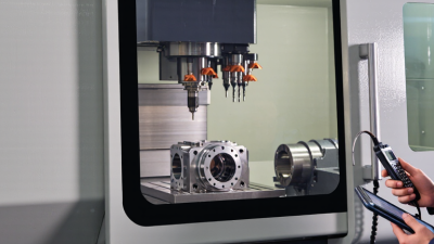
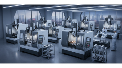
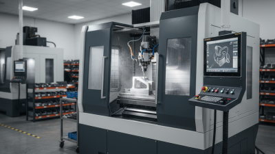
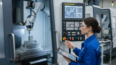
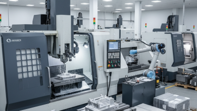
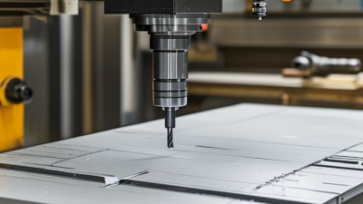
A CNC machining center is a computer-controlled machine tool that cuts, drills, and shapes material with repeatable precision. It commonly combines a spindle, a worktable, an automatic tool changer, and an enclosure. The operator secures a workpiece, loads a programmed toolpath, and checks that the setup matches the drawing. Then the machine follows coded instructions to remove material. In practice, small details matter: a loose fixture, worn tool, or incorrect offset can affect the finished part.
Many centers perform several operations without moving the workpiece between machines. A milling center, for example, may drill holes, machine slots, and finish flat surfaces during one setup. This can reduce handling and improve consistency, though it does not guarantee a perfect result. Tools still wear. Materials behave differently. Skilled setup and inspection remain essential. That part is easy to overlook.
This guide explains what a cnc machining center is, how its main components work, and how a typical machining cycle unfolds. It also clarifies common differences between machining centers and simpler CNC machines. Names and capabilities vary by manufacturer, so specifications should be checked before choosing equipment. Understanding the process helps readers ask better questions about accuracy, production time, maintenance, and cost. It is a practical starting point, not a substitute for machine-specific training or engineering review.
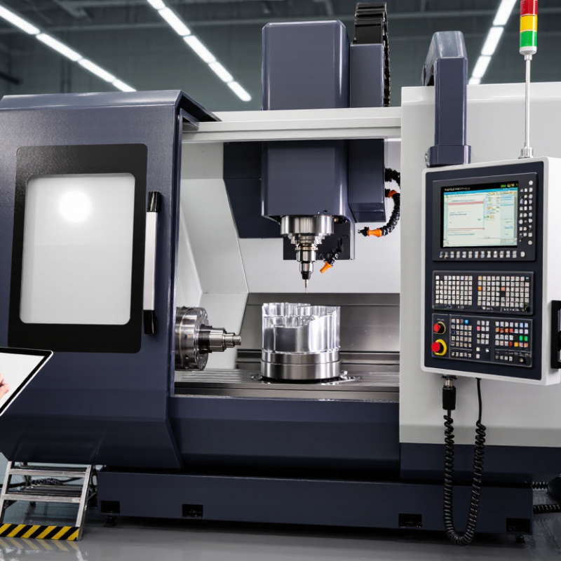
A CNC machining center is a computer-controlled machine tool built to perform several cutting operations in one setup. Its defining feature is an automatic tool changer, which moves tools between a magazine and the spindle without an operator changing each one by hand. The workpiece stays clamped while the machine mills, drills, or taps it. That matters.
Axis movement also helps define the machine. A three-axis center moves along X, Y, and Z; additional rotary axes can reach angled surfaces with fewer reclamps. An enclosure contains chips and coolant, while the control system follows programmed tool paths and cutting parameters. A pallet changer may support faster loading, but it is not essential to the definition. The label can be fuzzy: machine layouts and capabilities vary.
The scale of the sector shows why the distinction matters. Gardner Intelligence’s 2023 World Machine Tool Survey estimated global machine-tool consumption at $99.4 billion in 2022. That figure covers machine tools broadly, not machining centers alone. It is useful context, not proof that every center is productive. Real performance still depends on setup accuracy, tool condition, workholding, and operator skill. A precise machine can still produce a poor part.
A CNC machining center is a computer-controlled machine tool, typically equipped with an automatic tool changer, that performs operations such as milling and drilling. Common configurations combine three linear axes with zero, one, or two rotary axes. The chart shows axis counts, not a ranking of machine capability.
A CNC machining center works by coordinating a rigid structure, a cutting spindle, and computer-controlled axes. The bed and column support the workpiece and resist cutting forces; linear guides and ball screws move the table or spindle along programmed paths. Servo motors drive these axes, while encoders report position back to the controller. The spindle holds and rotates the tool, and an automatic tool changer swaps cutters when the program calls for a different operation. Small errors matter: a loose fixture or worn guide can leave visible steps on a machined surface.
The CNC controller reads the tool path, coordinates spindle speed and axis movement, and uses feedback to correct positioning. Coolant helps control heat, while the enclosure and chip-removal system manage spray and metal fragments. That matters. Grand View Research valued the global CNC machine market at $101.22 billion in 2023 and projected a 5.5% compound annual growth rate through 2030, reflecting broad industrial demand for precise machining. The International Federation of Robotics reported 541,302 industrial robot installations worldwide in 2023, a 10% annual increase; automation increasingly works alongside CNC equipment, though robots do not replace careful setup. A useful reminder: the controller can follow a program perfectly, yet the result still depends on sound tooling, calibration, and the operator’s judgment.
Preparing a CNC machining center begins with a clean, stable machine. The operator checks lubrication, coolant level, tool condition, and the work area before loading the program. Chips trapped under a fixture can tilt a part by a fraction of a millimeter. That small error may spoil a tight-tolerance feature. The table, vise, and locating surfaces are wiped clean, then the workpiece is clamped firmly without distortion. A setup sheet should identify the stock size, datum faces, fixture position, and required tools.
Next, the operator loads tools into the correct pockets and measures their lengths and diameters. Tool offsets are entered or checked with a presetter or the machine’s tool probe. The workpiece datum is then established using an edge finder, probe, or careful manual measurement. A dry run above the part helps reveal wrong offsets or unexpected toolpaths. Deloitte’s 2024 smart manufacturing survey reported that 86% of surveyed executives expect smart manufacturing to be a key competitiveness driver within five years. Digital measurement can support consistent setup, but it cannot replace a sound clamping check.
Tips: Keep the first toolpath conservative. Verify the part is seated against its stops, then confirm the spindle, coolant, and door interlocks. A probe can save time, yet a dirty stylus or loose fixture still misleads. I have seen a setup look perfect and still need correction. Recheck the first cut before running a full batch.
A CNC machining process begins with a digital part design and a defined sequence of cutting operations. CAM software turns that plan into toolpaths and machine instructions, including tool changes, spindle speed, and feed rate. An operator secures the stock in a vise or fixture, loads the tools, and sets the work zero. A setup error of just a few millimeters can spoil the part.
During cutting, the controller moves the tool and workpiece along programmed axes. The spindle rotates an end mill or drill, while coolant helps control heat and clear chips. The machine may mill a face, drill holes, and finish edges without the operator repositioning the part. That saves handling, but it does not remove the need for checks. Tool wear, vibration, or a loose clamp can shift dimensions, so operators inspect critical features with gauges or measuring instruments and adjust offsets when needed. Real workshops are messier than the ideal sequence.
Automation often supports this workflow. The International Federation of Robotics reported 4.28 million industrial robots operating worldwide in 2023, with 541,302 installed that year in its World Robotics 2024 report. Those figures cover industrial robots broadly, not CNC cells alone. Still, robot loading can let a machining center run between shifts, provided parts are presented consistently and safety interlocks work correctly. Automation helps; it is not a substitute for sound setup.
A CNC machining center is a computer-controlled machine that removes material using rotating cutting tools. The figures below are typical examples, not guaranteed specifications; actual capabilities depend on the machine, material, tooling, setup, and inspection method.
| Step | Process Stage | What Happens | Typical Data or Check |
|---|---|---|---|
| 01 | Part design and planning | A 3D CAD model or engineering drawing defines the part geometry, dimensions, material, and required features. CAM software is used to plan toolpaths. | Confirm units, drawing revision, material grade, critical dimensions, and tolerances before programming. |
| 02 | Workholding and setup | The workpiece is secured in a vise, fixture, or other workholding device. The operator establishes the part datum and sets the work coordinate system. | Work offsets such as G54 are commonly used. Check that the part is seated securely and that the setup clears the toolpath. |
| 03 | Program preparation | CAM software generates toolpaths, which are post-processed into machine-readable instructions. The CNC controller interprets commands for motion, spindle operation, and auxiliary functions. | Review tool numbers, coordinate systems, feeds and speeds, safe clearances, and program units before running the job. |
| 04 | Tool loading and measurement | Cutting tools are loaded into the tool magazine or spindle. The machine uses tool-length and, where required, tool-radius offsets to position each tool correctly. | Tool length offsets and tool condition should be verified. Automatic tool changers are common on machining centers, but magazine capacity varies by machine. |
| 05 | Material removal | The spindle rotates the cutting tool while machine axes move the tool and workpiece relative to one another. Operations can include milling, drilling, boring, and tapping. | A 3-axis center typically moves along X, Y, and Z. 4-axis or 5-axis machines add rotary motion for additional orientations or more complex access. |
| 06 | Coolant and chip control | Coolant or cutting fluid may reduce heat and help clear chips. Some processes use air blast, through-tool coolant, or dry cutting, depending on the material and operation. | Monitor chip evacuation, coolant flow where used, and signs of tool wear or excessive heat. Requirements vary with the cutting process and material. |
| 07 | In-process inspection | Selected features may be checked during machining using a touch probe or manual measuring tools. Measurements can be used to correct offsets or catch errors early. | Common checks include feature position, hole diameter, overall dimensions, and datum location. Use instruments appropriate to the required tolerance. |
| 08 | Finishing and final verification | Finishing passes complete surfaces and critical features. After machining, the part is cleaned and inspected against the drawing or inspection plan. | General machining tolerances are often around ±0.1 mm unless specified otherwise. Tighter tolerances may be achievable with suitable equipment, material, and process control. |
Machining centers are commonly classified by spindle orientation, axis capability, and workpiece size. A vertical machining center directs its spindle downward, making it practical for flat plates, pockets, and mold details. The operator can often see the cutting area clearly. A horizontal machining center uses a side-facing spindle and pallet systems to reach several faces with fewer manual repositioning steps. It suits heavier parts and repeat production. The layout matters.
Five-axis centers tilt or rotate the workpiece, or the cutting head, so a tool can reach angled surfaces in one setup. This reduces clamping changes, though programming and setup demand more skill. Gantry centers span large workpieces, such as structural panels, while mill-turn centers combine turning and milling for parts with both cylindrical and machined features. These categories overlap; machine choice depends on geometry, tolerance, batch size, and available floor space.
Automation is increasingly relevant to these choices. The International Federation of Robotics reported 541,302 industrial robot installations worldwide in 2023 in its World Robotics 2024 report. That figure covers industrial robots broadly, not machining centers alone, but it shows the scale of factory automation that cell-based machining may connect with. In practice, a horizontal center with a pallet changer can keep cutting while another part is loaded. It is not always the best answer. A simpler vertical machine may be easier to operate and maintain.