
Introduction: Why User Management in ZEISS CALYPSO Software is Important Managing user access in ZEISS…
Precision in metrology starts with the correct alignment of your tool rack. In this comprehensive guide, you’ll learn how to align a tool rack on a ZEISS Coordinate Measuring Machine (CMM) using a VAST XXT sensor. When aligned correctly, the rack allows smooth stylus system changes, minimizes machine wear, and ensures reliable measurements.
Required Equipment and Tools
Before you begin, make sure you have the following equipment on hand:
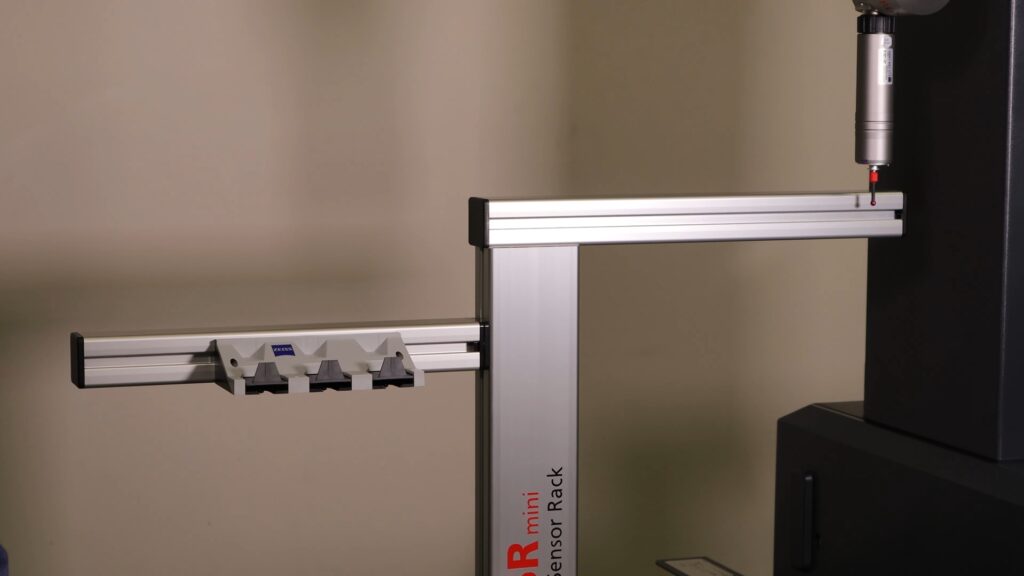
- Tool rack
- Changer bay for stylus systems
- Calibration sphere for stylus qualification
- Mounting hardware to secure the rack to the CMM
You’ll also need the master probe, which includes:
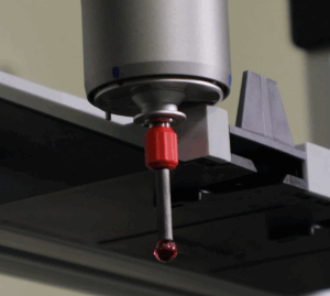
- An adapter plate typically marked with red painted dots
- A stylus with a red collar
MISSING SOMETHING? CONTACT US TO GET WHAT YOU NEED.
Step 1: How To Create and Activate a Stylus System
To begin, use the master probe to create a new stylus system in your CMM ZEISS CALYPSO software.
- Assign it a clear, recognizable name (e.g., “Tool Rack Alignment Setup”).
- Qualify two stylus orientations:
- Stylus 1 at 90° / 0°
- Stylus 2 at 180° / 0°
Be sure both styli in the stylus system created are qualified. This is critical – since each stylus will be used to align the tool rack.
Step 2: Initiate a New Measurement Plan
Next, initiate a new measurement plan or program.
Important: Do not configure a base alignment or define clearance planes yet. Why? Because the Tool Rack must align relative to the machine’s fixed coordinates—not to part geometry.
Step 3: Align the Tool Rack Physically
Now it’s time to perform the physical alignment:
- Switch to the 180° / 0° probe orientation.
- Use the stylus to probe a point on the far left side of rack.
- Use the stylus to probe a point on the far right side of rack
- In your software, generate a simple distance characteristic between the two Y-direction points.
The Y-distance difference must be less than or equal to 0.04 mm.
If the difference exceeds 0.04 mm (.0016 inches)
- Loosen the rack’s mounting hardware.
- Gently rotate or shift the rack to correct the alignment.
- Retighten the hardware.
- Repeat the probing process until the alignment falls within tolerance.
By the end of this step, your Tool Rack should be square and level to the machine axes.
WATCH HOW TO DO THIS IN OUR VIDEO
Step 4: Define and Calibrate Stylus Length
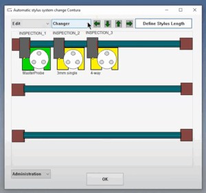
Open the ZEISS CALYPSO software and go to CNC Stylus System Change. Before you start, ensure you switch to the 90° / 0° probe orientation and click on “Define Stylus Length”, located in upper right corner.
- Use the master probe with the adapter plate to probe the outer corner of the changer bay.
- Avoid the central tab and inner surfaces.
- Focus contact on the adapter plate’s outer edge.
- Raise the probe after this contact.
- Now switch to the ruby stylus tip and probe the same exact corner.
This double-probing action determines the effective stylus length.
Verify that the calculated length falls between 35–36 mm. This ensures correct probe-to-holder alignment and prevents damage or crashes during automatic tool changes.
Length falling out of range? Contact our experts to get help.
Step 5: Align the Stylus Holder in Software
To confirm holder alignment:
- Open the stylus system interface.
- Left-click the far-left tool holder.
- If the icon turns green, alignment is successful.
- If it stays orange, the holder is still unaligned.
- Click on the down arrow by “Changer” and select for “Define Holder Location”.
- Confirmation window appears if a holder was previously aligned.
*If this confirmation doesn’t appear, your previous steps may need review—alignment was likely skipped or unsuccessful.
5. A window appears with directions on how to align the holder.
Step 6: Align Additional Stylus Holders
If your Tool Rack has multiple stylus slots, repeat the process for each one:
- Navigate to CNC Stylus System Change.
- Go to the Edit dropdown and select Add Stylus System Holder.
- Set the Holder Type to XXT.
- Assign a descriptive name to the new holder group (the new group of 3 holders will be in red, indicating they are not aligned)
- Repeat the probing and alignment steps (2 thru 5) to ensure tool rack is aligned with the same accuracy.
Final Thoughts
Proper Tool Rack alignment on your ZEISS CMM isn’t just a best practice—it’s essential. Accurate alignment enables seamless probe changes, safeguards against mechanical collisions, and maintains long-term reliability of your inspection process.
By following these steps carefully to align a tool rack on a ZEISS CMM, you ensure your system stays within tight tolerances and operates with minimal manual intervention.