Skip to content

What Are the Top 10 Types of Machining Centers?

Choosing the right machining center begins with understanding the workpiece, not the machine brochure. A compact vertical machining center may suit aluminum brackets, while a horizontal model can handle deep cavities with better chip evacuation. Five-axis machines reduce repeated setups. Gantry and bridge designs support large, heavy components. Each structure changes cutting access, rigidity, accuracy, cycle time, and operator workload.

As machining educator John Saunders often emphasizes, “The best machine is the one that fits the work.” That practical view matters on a real shop floor. A spindle running at 12,000 rpm means little if the table cannot support the part. A wide working envelope also creates problems when fixtures become difficult to reach. Small details decide productivity.

This guide examines the top 10 types of machining center, including vertical, horizontal, five-axis, gantry, bridge, universal, and mill-turn configurations. It compares their construction, typical applications, strengths, and limitations. The ranking is useful, but not absolute. A job shop cutting mold steel needs different priorities than an aerospace plant machining thin titanium walls. Tool access, coolant delivery, thermal stability, and maintenance history can matter more than headline specifications.

There is no perfect machine. Only a better match.

Some categories also overlap, which can confuse buyers. A universal machining center may include five-axis capability, while a mill-turn machine combines turning and milling functions. Careful evaluation remains essential. This overview provides a grounded starting point for engineers, purchasing teams, and shop owners seeking reliable machining performance.
What Are the Top 10 Types of Machining Centers?

What Is a Machining Center and How Does It Work?

A machining center is a computer-controlled machine that cuts, drills, taps, and sometimes turns metal or plastic parts. Unlike a basic milling machine, it can perform several operations with minimal manual intervention. Its automatic tool changer selects cutters from a stored tool magazine. The spindle then rotates each tool at a programmed speed. Raw stock is secured on the worktable. That sounds simple. In practice, accurate setup matters as much as advanced hardware.

The process begins with a digital part model and a cutting program. The control system converts programmed instructions into coordinated axis movements. Linear axes position the workpiece, while rotary axes can tilt or rotate it. Coolant reduces heat and carries chips away from the cutting zone. Sensors and inspection routines can help detect tool wear, poor alignment, or dimensional drift. An operator still checks workholding, tool length, offsets, and the first finished part. Automation does not remove responsibility.

The ten commonly discussed types include vertical, horizontal, three-axis, four-axis, five-axis, gantry, high-speed, drilling-tapping, mill-turn, and micro machining centers. These categories overlap, which can make comparisons confusing. A vertical center suits many general components and offers clear access from above. A horizontal design often improves chip removal during deep cavity work. Five-axis equipment reaches complex surfaces with fewer setups, but programming and verification become harder. Mill-turn machines combine rotating and milling operations, although they demand careful process planning. The “best” center depends on material, tolerance, part geometry, production volume, and operator skill. A technically impressive machine can still underperform when fixtures are weak or cutting data is poorly tested.

How Machining Centers Are Classified by Axis Configuration

What Are the Top 10 Types of Machining Centers?

How Machining Centers Are Classified by Axis Configuration

Machining centers are often classified by controlled axes, not spindle power. A three-axis vertical center moves along X, Y, and Z. A three-axis horizontal center uses the same linear logic, but changes chip evacuation and fixture access. Four-axis models add a rotary table. They suit parts needing repeated side machining. Five-axis indexed centers rotate the workpiece between cuts. Simultaneous five-axis centers move all axes together. They handle turbine blades, molds, and complex medical components. Six-axis centers add another rotary movement for deeper access. Mill-turn centers combine milling and turning in one setup. Gantry centers provide large travel for molds and structural parts. Double-column centers improve rigidity on wide workpieces.

Axis count does not automatically mean higher productivity. Fixture design, control quality, and operator skill still matter. In daily production, I have seen a well-set three-axis machine outperform a poorly programmed five-axis machine. That detail is easy to ignore. MarketsandMarkets’ 2024 machining centers analysis identifies automation and multi-axis capability as major market drivers. Grand View Research’s 2024 machine tools report also places Asia-Pacific above half of global demand, reflecting strong automotive and electronics production.

A useful selection method begins with access requirements. Choose four-axis machining for repeated angled features. Consider indexed five-axis work when setups create alignment errors. Use simultaneous five-axis machining when tool orientation changes continuously. Large aerospace structures may require gantry configurations. Tight spaces may favor horizontal layouts. These categories overlap, and reports do not always define “axis” consistently. That is a weakness worth checking before comparing market figures or machine quotations.

What Are the Top 10 Types of Machining Centers?

What Are the Top 10 Types of Machining Centers?

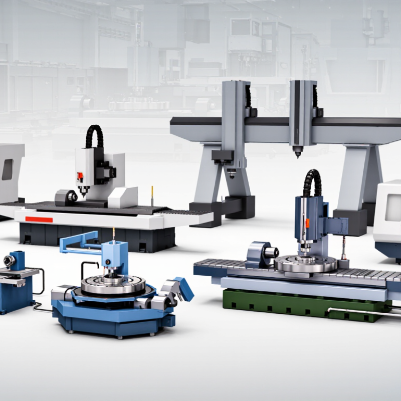
The top ten types of machining centers vary by structure, movement, and production purpose. Vertical machining centers are common for general milling, drilling, and precise fixture work. Horizontal machining centers handle heavy parts and improve chip removal during deep cutting. Three-axis centers suit straightforward components with flat surfaces. Four-axis models add rotary positioning for better access to multiple faces.

Five-axis machining centers reach complex contours with fewer setups. Gantry machining centers support large workpieces, such as molds, frames, and aircraft structures. Bridge machining centers offer strong rigidity and stable cutting across wide work areas. Double-column centers are built for oversized parts and demanding material removal. Mill-turn centers combine milling and turning, reducing transfers between machines. Drilling and tapping centers focus on fast hole-making and threaded features.

These categories often overlap. A five-axis machine may also use a gantry structure, which makes simple labels imperfect. In my experience, choosing the right center depends on tolerance, part size, tooling access, and production volume. A compact vertical center may outperform a larger machine on small aluminum parts. Heavy steel components usually need greater rigidity and torque. Operators should also inspect spindle speed, table load, axis travel, coolant delivery, and control usability. Small details matter. I once underestimated fixture access on a complex part, creating unnecessary rework. Machine capability alone does not guarantee reliable results. Good process planning, measurement, and realistic cycle-time testing remain essential.

Key Features and Applications of Each Machining Center Type

What Are the Top 10 Types of Machining Centers?

Machining centers differ by spindle direction, axis movement, work envelope, and automation. Vertical machining centers offer clear visibility and strong chip access. They suit molds, brackets, and general production. Horizontal machining centers use pallets and better chip evacuation. They are effective for deep cavities and multi-face parts. Three-axis centers remain practical for flat surfaces and simple contours. Four-axis models add rotary positioning for indexed side machining. Five-axis centers reach complex surfaces with fewer setups. They support aerospace components, medical parts, and precision prototypes.

Gantry and bridge machining centers handle large plates, dies, and structural parts. Their rigid frames reduce vibration across wide work areas. Double-column centers provide additional support for heavy cuts. Mill-turn centers combine milling and turning in one setup. This can reduce alignment errors, though programming becomes more demanding. Drilling and tapping centers prioritize speed, compact tools, and repeated hole patterns. Each type has limits. A large machine may waste energy on small parts, while a compact center may struggle with oversized workpieces.

Tips: Match the machine to material, tolerance, part size, and batch volume. Check spindle torque, tool capacity, axis travel, and coolant delivery. Watch a test cut when possible. Real shop conditions can expose vibration, heat, or access problems. I have found that setup time often matters more than advertised speed. Review maintenance access and operator training before purchasing.

What Are the Top 10 Types of Machining Centers? – Key Features and Applications of Each Machining Center Type

Machining Center Type Primary Spindle Orientation Typical Axis Configuration Key Features Main Advantages Common Applications Best Suited For
1. Vertical Machining Center (VMC) Vertical spindle; tool approaches the workpiece from above. 3-axis to 5-axis Compact layout, accessible work area, automatic tool changer, and a table that generally supports straightforward fixture loading. Lower initial cost, simple programming, good visibility, and efficient chip removal on many open-top parts. General-purpose milling, drilling, tapping, die and mold work, and production of prismatic components. Small to medium components, prototype work, job-shop production, and operations requiring frequent setup changes.
2. Horizontal Machining Center (HMC) Horizontal spindle; the tool approaches the workpiece from the side. 3-axis to 4-axis Often equipped with a rotary pallet system, multiple work surfaces, and a spindle positioned for effective chip evacuation. Good access to several sides of a workpiece, reduced chip recutting, and strong suitability for continuous production. Automotive components, gearbox housings, hydraulic blocks, engine parts, and other multi-sided prismatic parts. Medium to high production volumes where fewer setups and reliable unattended cycles are important.
3. 5-Axis Machining Center Vertical or horizontal, depending on machine design. Simultaneous 5-axis Three linear axes plus two rotary axes allow the cutting tool to approach a part from multiple directions in one setup. Fewer setups, improved access to complex surfaces, shorter tools, better surface quality, and reduced fixture-related errors. Aerospace structural parts, impellers, turbine blades, medical components, complex molds, and sculptured surfaces. Complex geometries, tight positional requirements, and parts that are difficult or impossible to complete efficiently on 3-axis equipment.
4. Universal Machining Center Usually vertical or swiveling; spindle and/or table can be reoriented. 3+2-axis or 5-axis Combines conventional milling capability with an articulating head, tilting table, or rotary trunnion for multi-face machining. Flexible setup options, strong access to angled features, and the ability to handle varied workpieces in one machine. Toolmaking, aerospace parts, general engineering, maintenance work, and low-volume production of complex components. Manufacturers needing broad process flexibility rather than a machine dedicated to one part family.
5. Gantry or Bridge Machining Center Typically vertical, mounted on a movable crossrail or bridge. 3-axis to 5-axis Large work envelope, rigid bridge structure, long travel ranges, and support for large tables or oversized fixtures. High structural stability, accurate machining over large areas, and the ability to process wide or heavy workpieces. Aircraft structures, energy equipment, large molds, shipbuilding components, and heavy industrial parts. Large-format workpieces that exceed the capacity of conventional column-and-table machining centers.
6. Double-Column Machining Center Usually vertical, with a spindle head supported between two columns. 3-axis to 5-axis Two rigid columns support a crossbeam, improving stiffness and reducing deflection during heavy cutting. High rigidity, strong cutting performance, good dimensional stability, and suitability for deep or heavy material removal. Large dies, construction machinery parts, heavy equipment frames, energy components, and large molds. Heavy-duty milling of large, wide, or difficult-to-machine components requiring high structural stiffness.
7. High-Speed Machining Center Most commonly vertical, although horizontal versions are available. 3-axis to 5-axis High spindle speed, rapid acceleration, fast tool changes, low-vibration construction, and control systems optimized for short blocks of code. Shorter cycle times, excellent surface finish, reduced cutting forces, and efficient machining of small tools and fine details. Electrodes, precision molds, aluminum components, medical parts, electronics housings, and detailed prototypes. Small to medium parts requiring fast feed rates, fine surface finishes, and high geometric detail.
8. Drilling and Tapping Center Usually vertical. 3-axis to 4-axis Compact design, rapid positioning, high-speed drilling and tapping cycles, and quick automatic tool changes. Very high productivity for hole-making, efficient floor-space usage, and low cycle times for repetitive operations. Flange production, electronics components, small automotive parts, fittings, brackets, and fastener-hole patterns. Small parts with many holes, threads, chamfers, and light milling operations produced in medium or high volumes.
9. Mill-Turn Machining Center Turning spindle with a live-tool milling spindle; orientation varies by design. Multi-axis Combines turning, milling, drilling, tapping, and sometimes sub-spindle operations in a single coordinated platform. Complete machining in fewer setups, reduced work-in-process, better alignment between features, and shorter overall lead times. Flanges, shafts, valve bodies, couplings, hydraulic components, and parts combining cylindrical and milled features. Complex rotational parts that would otherwise require separate turning and milling machines.
10. Horizontal Boring and Milling Center Horizontal spindle, often with a boring spindle or extendable quill. 3-axis to 5-axis Designed for deep boring, large-diameter holes, heavy milling, and machining of large workpieces with substantial reach. Excellent hole accuracy, long tool reach, strong heavy-cutting capability, and effective access to internal features. Machine bases, engine blocks, pump housings, gear cases, structural castings, and large industrial assemblies. Large and heavy components requiring precise bores, deep internal machining, or extensive material removal.

How to Choose the Right Machining Center for a Specific Job

What Are the Top 10 Types of Machining Centers?

How to Choose the Right Machining Center for a Specific Job

The ten common types include vertical, horizontal, three-axis, four-axis, five-axis, gantry, bridge, drilling-tapping, mill-turn, and double-column centers. Selection should begin with the part, not the machine brochure. Review material hardness, workpiece size, tolerance, surface finish, and monthly volume. A vertical three-axis center suits accessible prismatic parts. A horizontal center improves chip evacuation on deep cavities. Five-axis machining becomes valuable when several angled faces require one setup.

Fixture access matters greatly. Check spindle torque, taper size, table load, tool capacity, and working envelope. For long aerospace-style components, a gantry or bridge structure may reduce repositioning. For compact aluminum parts, a high-speed drilling-tapping center can shorten cycle time. The International Federation of Robotics reported 541,302 industrial robot installations worldwide in 2023. That figure supports evaluating robot access, pallet changing, and unattended operation early.

Energy and maintenance also affect the real cost. The U.S. Department of Energy identifies motor-driven systems as major industrial energy users, so spindle efficiency and idle consumption deserve measurement. I have seen teams overbuy five-axis capability for simple parts. That decision can create training delays and unused capital. The opposite mistake is worse: choosing a small machine for heavy cuts, then losing accuracy through vibration. Test the hardest material, largest fixture, and longest tool before purchase. Perfect predictions are rare. A witnessed cutting trial is better.

Back To Top